




RTK technology now plays a role in more than just surveying. Farmers use it to guide tractors, construction teams rely on it for excavator positioning, and it helps robot mowers follow set boundaries and drones geotag aerial images. While much of the focus often falls on the receiver, the RTK antenna also plays an important role in positioning accuracy and signal stability. This guide looks at how an RTK antenna works, which specifications matter when choosing one, recent developments in the technology, and what to consider for different applications.

1. What an RTK Antenna Does
How RTK positioning works
- RTK (real-time kinematic) positioning uses carrier-phase measurements from satellite signals received by a rover and a reference station at a known location. The reference station, or a network of stations, calculates correction data and sends it to the rover through a radio link or the internet. Many systems use NTRIP to deliver these corrections in RTCM format.
- The rover combines the correction data with its own carrier-phase measurements to resolve the integer ambiguities in the satellite signals. When conditions are suitable, this allows an RTK system to achieve centimetre-level positioning accuracy, compared with the metre-level accuracy typical of standalone GNSS. The RTK antenna provides the satellite signals that the receiver needs for these measurements. It must support the required frequency bands and maintain consistent phase characteristics so the receiver can make reliable measurements and resolve ambiguities.
Why the antenna can matter more than the module
- A receiver depends on the antenna to deliver clean, reliable satellite signals. If the antenna has a poor axial ratio, it may handle reflected signals less effectively, allowing multipath to interfere with carrier-phase measurements. The antenna’s phase centre can also shift as satellites move across the sky, adding positioning errors even when the receiver has a clear view of the satellites.
- Receiver datasheets often assume a suitable antenna, but actual performance depends on both components working well together. A well-designed RTK antenna can make a real difference, even when paired with a mid-range receiver. In some cases, this combination may deliver more consistent positioning than a high-end receiver connected to a poorly matched antenna. That’s one reason devices with the same receiver module can produce different results in real-world conditions.
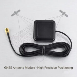
2. Specifications That Affect RTK Performance
Frequency coverage and band combinations
- RTK receivers use signals from multiple frequency bands to improve positioning accuracy. Dual-band and multi-band reception helps them estimate and correct ionospheric delays, which can cause larger errors over longer baselines. Depending on the application, a high-precision RTK antenna may cover GPS L1/L2/L5, Galileo E1/E5a/E5b, BeiDou B1/B2/B3 and GLONASS L1/L2. Some designs also support L-band signals for satellite-based correction services.
- Frequency coverage is only part of the picture. An antenna also needs to maintain consistent gain and radiation patterns across its operating bands. Poor performance near the edges of a frequency band can weaken satellite signal reception and affect the receiver’s ability to maintain a reliable positioning solution.
Phase centre stability
- The phase centre is the apparent point from which an antenna receives satellite signals. Its position can vary with frequency and satellite elevation angle. Survey-grade antennas are therefore tested and calibrated for phase centre offset (PCO) and phase centre variation (PCV), giving users the data they need to account for these differences.
- These variations can affect RTK positioning when an application calls for consistent measurements over time. In static surveying, they can reduce measurement repeatability. In machine control, they may lead to small but persistent positioning errors. A calibrated RTK antenna generally costs more, but its PCO and PCV data help users account for phase centre behaviour in demanding applications. For surveying and other precision work, this calibration is an important part of achieving reliable measurements.
3. RTK, PPP and PPP-RTK: What Changed Recently
How the three approaches compare
| Approach | Correction source | Typical accuracy | Convergence |
| RTK, single base | Local base station over radio or IP | Centimetre-level | Seconds after ambiguity fix |
| Network RTK | CORS network over NTRIP | Centimetre-level | Seconds to about a minute |
| PPP | Precise orbit and clock products | Decimetre-level | Minutes |
| PPP-RTK | State-space corrections with ambiguity resolution | Centimetre-level | A few minutes |
The table is a simplification. Real performance depends on baseline length, sky view, satellite geometry and the quality of the corrections, so the same receiver can move between categories from one site to the next.
Free correction services are changing the economics
- Galileo’s High Accuracy Service provides free precise point positioning corrections, with a target horizontal accuracy of 20 cm at the 95% level. Users receive the corrections directly through satellite broadcasts, without paying a subscription fee. This makes the service a practical option for devices that may not need a full network RTK service.
- BeiDou offers a similar service through PPP-B2b, broadcasting free corrections across the Asia-Pacific region. Published studies have reported centimetre-level accuracy in static conditions and decimetre-level accuracy while moving. For products sold globally, manufacturers need to consider regional service coverage and ensure the RTK antenna supports the signals and frequency bands available in each market.
Receiver platforms and correction delivery are moving
- In September 2024, u-blox introduced the X20, an all-band high-precision GNSS platform, and launched its first product, the ZED-X20P, in March 2025. The module delivers centimetre-level positioning. As manufacturers gain access to more affordable all-band receivers, they also need an RTK antenna that performs reliably across a wider range of frequencies.
- Correction services are changing alongside receiver technology. In May 2025, u-blox announced PointPerfect Global, aiming to bring high-precision corrections to areas where network RTK coverage is limited. The company currently plans to make the service generally available in Q4 2026, with satellite L-band delivery expected in 2027.
4. Choosing an RTK Antenna by Application
Surveying and GIS
Surveyors need an antenna that maintains a stable phase centre and delivers repeatable measurements. They often use a calibrated RTK antenna with a choke ring or a large ground plane to reduce multipath interference. Portability matters as well, so they must weigh the benefits of a larger ground plane against the added size and weight of the equipment.
Agriculture and autonomous machinery
Tractors and sprayers need steady positioning as they move through fields, often around trees, buildings and the machine’s own metal structures. In these conditions, an RTK antenna needs a rugged housing, a secure mount and good signal reception at low satellite elevation angles. These features can matter more than peak gain alone. Dual-antenna heading systems also require a good match between the two antennas, as differences in their performance can affect heading accuracy.
Construction and machine control
Excavators, dozers and graders operate close to steel and concrete surfaces, where reflected signals can cause significant multipath interference. Operators often mount the RTK antenna on a mast or the machine’s counterweight to improve sky visibility, but these positions can require long cable runs. Designers therefore need to consider cable loss and filtering alongside the antenna’s radiation performance.
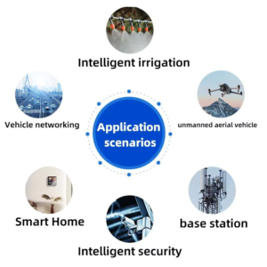
5. Installation and Integration Notes
Ground plane and mounting
- Most high-precision antennas rely on a ground plane, and manufacturers usually specify the required size. Mounting an RTK antenna on a plastic panel instead of a metal roof can change its resonance and radiation pattern. This is one reason an antenna may perform differently in the field than it does on the test bench.
- Mounting height brings its own trade-offs. Raising the antenna above nearby obstructions gives it a clearer view of the sky, but also means using a longer cable and dealing with greater exposure to wind and vibration. In many cases, a short, rigid mast with a proper seal works better than a tall, flexible one.
Cable loss and connectors
- Cable loss adds to the system’s noise budget, and longer cables generally lose more signal, especially at higher frequencies. A cable that performs well at L1 may not work as well at L5 or L-band. Check its attenuation at the highest frequency your system uses rather than relying on figures from the middle of the band.
- Connector choice also matters. Each extra connector adds a little loss and creates another potential point of failure. Make sure the RTK antenna connector matches the receiver port. Otherwise, the system may pass initial bench tests but deliver poorer performance after installation.
6. Conclusion
An RTK antenna does more than receive satellite signals; it also affects positioning accuracy and stability. Its frequency coverage, phase centre stability, axial ratio and filtering all influence the receiver’s ability to resolve and maintain carrier-phase ambiguities. The right choice depends on the application, including satellite visibility, mounting conditions, cable length and the correction service in use. Rather than relying on specifications alone, test the antenna in its actual enclosure and connect it to the receiver you plan to use. This helps reveal how nearby batteries, modems and other components affect its performance in the finished product.
7. FAQ
Q1: Does an RTK antenna need to support multiple frequency bands?
For most centimetre-level RTK applications, a dual-band or multi-band antenna is a better choice. It gives the receiver access to signals on different frequencies, helping it estimate and correct ionospheric errors, especially over longer baselines. Single-frequency RTK can still work over short baselines, but it offers less flexibility and may struggle to maintain a reliable fixed solution under less favourable conditions.
Q2: What is the difference between RTK and PPP?
RTK uses corrections from a nearby base station or reference network to achieve centimetre-level positioning. Once the receiver fixes its carrier-phase ambiguities, it can often deliver a solution within seconds. PPP takes a different approach: it uses precise satellite orbit and clock corrections, so users do not need a nearby base station. However, the receiver needs time to converge. Depending on the correction service, receiver and operating conditions, PPP can reach decimetre- or centimetre-level accuracy.
Q3: Can I use a standard GPS patch antenna with an RTK receiver?
A standard GPS patch antenna can receive satellite signals and provide a position, but that does not mean it will perform well in an RTK system. Many basic patches support only one frequency band and may lack the phase centre stability and multipath rejection needed for precision positioning. Choose an antenna that covers your receiver’s frequency bands and provides suitable phase performance. Even a high-end receiver cannot make up for every limitation in the antenna.
Q4: Why does my RTK receiver stay in Float instead of reaching a Fixed solution?
A receiver may remain in Float for several reasons. Poor satellite visibility, multipath from nearby buildings or metal surfaces, weak signals, long baselines and problems with correction data can all prevent it from fixing ambiguities. Incorrect antenna height or phase centre settings can also affect the position. Before changing the antenna or receiver, check the sky view, correction age, data link, antenna installation and receiver settings.
Q5: Does coaxial cable length affect RTK antenna performance?
Yes. Longer coaxial cables introduce more signal loss, and the loss generally increases at higher frequencies. This reduces the signal level reaching the receiver. If you use an active GNSS antenna, also check whether the receiver can supply enough voltage through the cable to power its built-in LNA. For longer cable runs, choose a low-loss cable and check both RF attenuation and DC voltage drop at the highest operating frequency.